Failure Before Downtime: A Quarry Drilling FMEA for Turnkey Projects
A quarry failure does not begin when the rig stops. It begins when a pattern assumption, equipment interface, measurement method, or field response can no longer protect the intended hole geometry and nobody has yet recognised the loss of control.
Table of Contents
The Rig Was Still Running. The Failure Had Already Started.
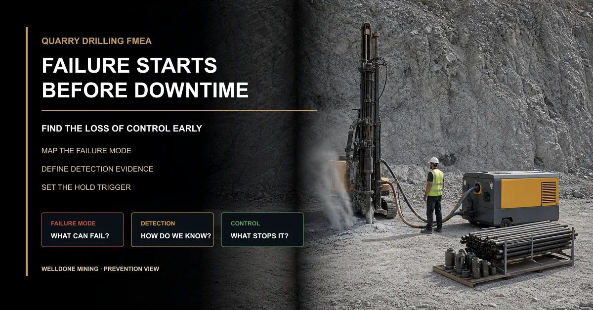
The rig kept drilling. Penetration slowed slightly near the end of the row, but the shift still reported completed metres. A hose connection showed a small leak, the bit face wore unevenly, and cuttings return became less consistent with depth.
None of those signals stopped the machine. The hole log still showed the planned depth.
After the blast, the loader found a hard strip along the floor and a concentrated coarse zone. Only then did the project call it a failure.
The real question is not whether the rig can continue. It is whether the drilling system can still prove that it is delivering the controlled geometry and hole condition required by the project.
Use FMEA to Prevent Failure, Not Explain It Later
Failure Mode and Effects Analysis, or FMEA, asks how each part of the work could fail, what the consequence would be, how the team would detect it, and which control should prevent or contain it. In quarry drilling , the “part” may be a design assumption, survey handoff, rig setup, air connection, tool interface, measurement step, or exception decision.
The method should be practical. It is not a ranking exercise performed once for the tender file. The register must connect each credible failure mode to an observable field signal, a named owner, and a response that the shift can execute.
A common mistake is to list only catastrophic equipment breakdowns. Many costly quarry failures occur while every major machine remains operational: collars are moved informally, cleaning degrades, tool wear changes hole behaviour, replacement holes lose identity, or the blast result cannot be traced to the drilled batch.
FMEA Field Project Question Required Evidence Weak Version to Avoid
Failure mode How can the design, equipment, execution, or evidence chain lose control? Specific condition tied to one location, interface, or work step “Poor drilling” or “operator error” without a mechanism Effect What changes in the hole, workfront, muckpile, loading, or crusher? Field consequence that can be observed or measured Generic “low efficiency” with no operational result Cause Which condition can create the failure mode? Design basis, equipment state, geology, method, or interface record Assigning blame before testing the mechanism Current control What prevents the failure or detects it before downstream exposure? Method, frequency, owner, acceptance rule, and record “Inspect regularly” without defining who, when, or how Response What happens when the trigger is reached? Hold, inspect, correct, approve, rework, or escalate route Continuing until the next planned maintenance window
Map Hole-Pattern Failure Modes Before Drilling
A hole pattern is a controlled relationship between the bench, free face, collars, hole paths, depths, and the qualified blast-design basis. Failure begins when the field arrangement no longer matches that basis or when the team cannot prove the final arrangement.
Pattern FMEA should begin with the actual workfront. Ask what could invalidate the survey reference, prevent the rig from using the planned setup, change the hole path, reduce usable depth, or force an unapproved replacement.
In my view, the best control plan does not attempt to predict every geological surprise. It makes surprises visible early enough for the qualified parties to decide before the crew turns an exception into a new, undocumented pattern.
The verified quarry blast hole pattern design guide explains burden, spacing, subdrill, stemming, deviation, air demand, and equipment matching. Site-specific blast design and regulated execution remain with qualified local professionals.
Pattern Failure Mode Likely Effect Prevention or Detection Control Escalation Trigger
Collar mark differs from the controlled revision Actual burden or spacing changes before drilling begins Revision check, survey reference, hole ID, and pre-drill reconciliation Field mark cannot be matched to one approved hole Rig cannot use the planned setup position Inclination, collar position, access, or sequence changes informally Workfront-access review and setup verification before collaring Operator must relocate or change alignment outside the agreed rule Hole path becomes unstable Bottom geometry differs even if collar and nominal depth appear correct Setup, tool condition, drilling response, geology notes, and deviation evidence where required Directional behaviour repeats across a row or geological zone Usable depth differs from logged progress Bottom relationship and floor outcome become uncertain Cleaning observation, blockage record, measurement method, and final-hole condition Depth cannot be verified under the defined method Replacement hole loses the original identity Final pattern cannot be reconstructed or reviewed correctly Original ID, reason, approver, replacement ID, and revised map New collar is proposed without an authorised disposition
Treat the Equipment List as an Interface Control Plan
The equipment list should describe how the drilling chain stays compatible, observable, and recoverable. A rig, compressor, hammer, bit, rods, and adapters can each meet a catalogue specification yet fail as a system because one interface is unsuitable, worn, leaking, unavailable, or poorly maintained.
Review every transfer point: engine to compressor, compressor to hose, hose to rig, rig to hammer, hammer to bit, rods to adapters, operator to measuring tool, and maintenance team to critical spares. Failure often enters at the connection, not the largest machine.
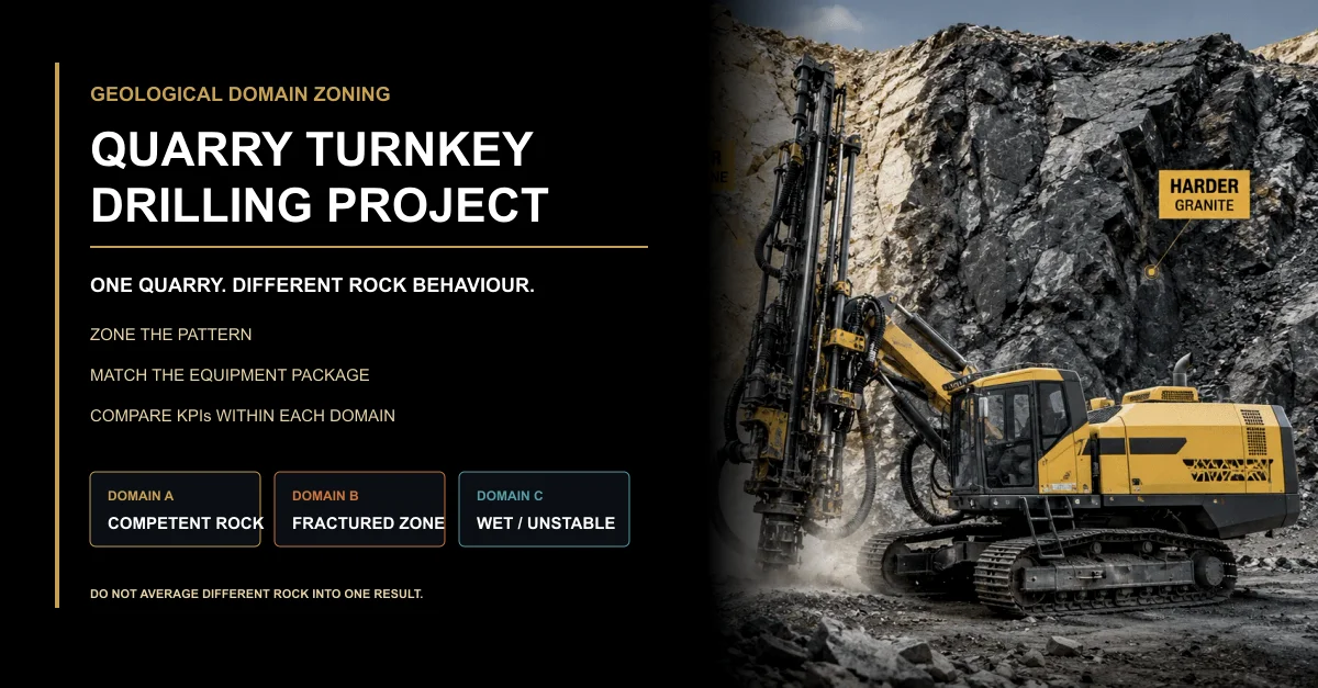
Welldone Mining’s verified customized drilling solution matches rigs, air compressors, bits, rods, DTH hammers, adapters, accessories, spares, and support to formation, diameter, depth, access, and operating conditions.
Equipment Interface Failure Mode Early Signal Control Required
Rig setup and feed system Position, mast alignment, or feed behaviour drifts during the batch Repeated setup correction, unstable feed, or shift-dependent hole behaviour Setup check, operating limits, maintenance condition, and linked hole IDs Compressor and air path Delivered duty falls below the requirement at the hole Leakage, heat, unstable pressure, weak cuttings return, or depth-related cleaning loss Pressure-flow basis, hose route, connection inspection, leakage check, and operating record Hammer, bit, rods, and adapters Energy transfer, connection integrity, or drilling stability deteriorates Abnormal wear, vibration, connection damage, short life, or changing penetration behaviour Compatibility list, wear criteria, inspection frequency, handling method, and starter quantities Lubrication and service system Routine condition loss develops into tool or machine damage Consumption change, temperature, contamination, unusual sound, or repeated minor faults Service schedule, condition checks, correct consumables, tools, and named owner Critical spares and recovery tools A routine field fault becomes extended downtime or uncontrolled substitution Minimum stock breached, replenishment delayed, or required tool unavailable Criticality list, minimum level, reorder trigger, compatible substitute rule, and recovery procedure
Define Detection Before the Signal Appears
A control is not credible unless the project knows what will be observed, who will observe it, when the check occurs, and how the evidence will be recorded. “Operator to monitor” is not a complete detection plan.
Some failures can be prevented at configuration lock. Others must be detected during setup, collaring, drilling, hole completion, batch handover, or downstream evaluation. The detection point should be placed before the consequence becomes expensive or irreversible.
More importantly, detection quality matters. A check that depends entirely on memory, subjective wording, or an unlinked spreadsheet may identify a symptom but still fail to protect the project decision.
Control Point What Must Be Detected Minimum Evidence Failure of the Control Itself
Before mobilisation Mismatch between site duty and proposed package Formation, diameter, depth, access, air demand, environment, and scope review Tender assumptions remain unverified or contradictory Before drilling each workfront Wrong revision, inaccessible setup, geological change, or unresolved constraint Release map, survey confirmation, visible-condition review, and approval status Checklist signed without reconciling physical conditions During drilling Drift in air, tool, setup, cleaning, penetration, or hole behaviour Hole-linked observations, equipment state, exceptions, and shift context Only total metres are recorded At hole completion Uncertain depth, blockage, collapse, replacement, or missing identity Final condition, method, disposition, approval, and updated map Nominal plan values are copied into the as-drilled record After the blast Toe, oversize, fragmentation band, difficult loading, or crusher disruption by batch Location, batch identity, consistent observation method, and downstream context Result is averaged across unrelated zones or operating states
Set Hold and Stop Triggers Before Production Pressure Arrives
The team should not invent the stop rule while the rig, crew, and compressor are waiting. Production pressure makes ambiguous signals easy to normalise.
Triggers can be numerical where the qualified project basis supports a number, or conditional where evidence is procedural. Examples include an unreconciled collar, an unverified hole condition, repeated abnormal wear, unstable air delivery, missing replacement approval, or an expired workfront release.
The trigger must lead to a defined action: hold one hole, isolate one row, inspect the air path, replace a worn component, remeasure, request qualified review, or suspend the batch. Not every trigger stops the entire quarry.
Trigger Type Example Condition Immediate Containment Release Requirement
Identity trigger Hole or revision cannot be matched to the controlled map Hold the affected collar or row Survey and design records reconciled with physical marks Equipment-condition trigger Repeated leakage, abnormal wear, connection damage, or unstable operating signal Stop the affected equipment chain and inspect interfaces Cause corrected, compatible components restored, and condition check recorded Hole-condition trigger Depth, cleaning, blockage, collapse, or path behaviour cannot be verified Hold the hole and prevent informal substitution Disposition approved and final identity recorded Pattern trigger Similar exceptions cluster across a row or zone Hold further drilling in the affected area Geology, setup, equipment, and qualified design basis reviewed Evidence trigger Batch result cannot be linked to as-drilled holes or operating state Do not use the result to justify a broad change Traceability restored or a controlled new comparison planned
Link Blast-Efficiency Signals to Supported Failure Modes
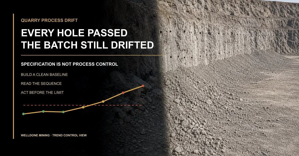
Toe, oversize, irregular fragmentation, difficult loading, secondary breaking, and crusher interruption are effects. They are not automatic proof of one drilling failure.
Geology, free-face condition, as-drilled geometry, hole condition, regulated blast inputs, loading practice, haulage, and plant state can interact. FMEA provides hypotheses and evidence requirements; qualified investigation determines which mechanism is supported.
The verified guide to quarry blast efficiency evaluation covers fragmentation, oversize, toe, muckpile, compliance evidence, and repeatable comparison.
Observed Effect Possible Failure Modes to Test Evidence Needed Unsafe Shortcut
Toe or high floor Depth uncertainty, hole-path change, pattern assumption, geology, or regulated-input issue Floor map, hole IDs, depth method, path evidence, geology, and qualified review Blame the operator from the floor appearance alone Localized oversize Local geometry change, blocked or replacement hole, geological boundary, or regulated-input variation Oversize location, final pattern, exception record, geology, and batch identity Change the complete quarry pattern after one localized result Irregular fragmentation band Repeated setup, air, wear, cleaning, path, geology, or loading variation Row sequence, equipment state, as-drilled map, observations, and comparable batch Average the band into one fragmentation number Difficult loading Toe, pile geometry, access, fragmentation, loader match, or operating method Loader feedback, floor condition, pile map, route, and shift context Treat every slow cycle as poor breakage Crusher interruption Oversize, inconsistent feed, dispatch gap, plant condition, or upstream shortage Interruption code, feed observation, loading and haulage context, and batch identity Assign all crusher loss to the blast
Close the Loop Without Turning FMEA Into Paperwork
The FMEA should change when field evidence changes. A recurring leakage point, wear pattern, blocked-hole mechanism, or traceability gap should update the control plan, equipment scope, inspection frequency, spare strategy, or training need.
Do not add a new form after every incident. Strengthen the control closest to the failure mechanism. If the cause was an incompatible interface, correct configuration control. If detection failed, improve the method and record. If the response failed, clarify authority and the release condition.
Review actions by workfront and batch, not only by calendar month. Close an action when the control has been implemented and demonstrated under comparable conditions—not when the meeting minutes say “completed.”
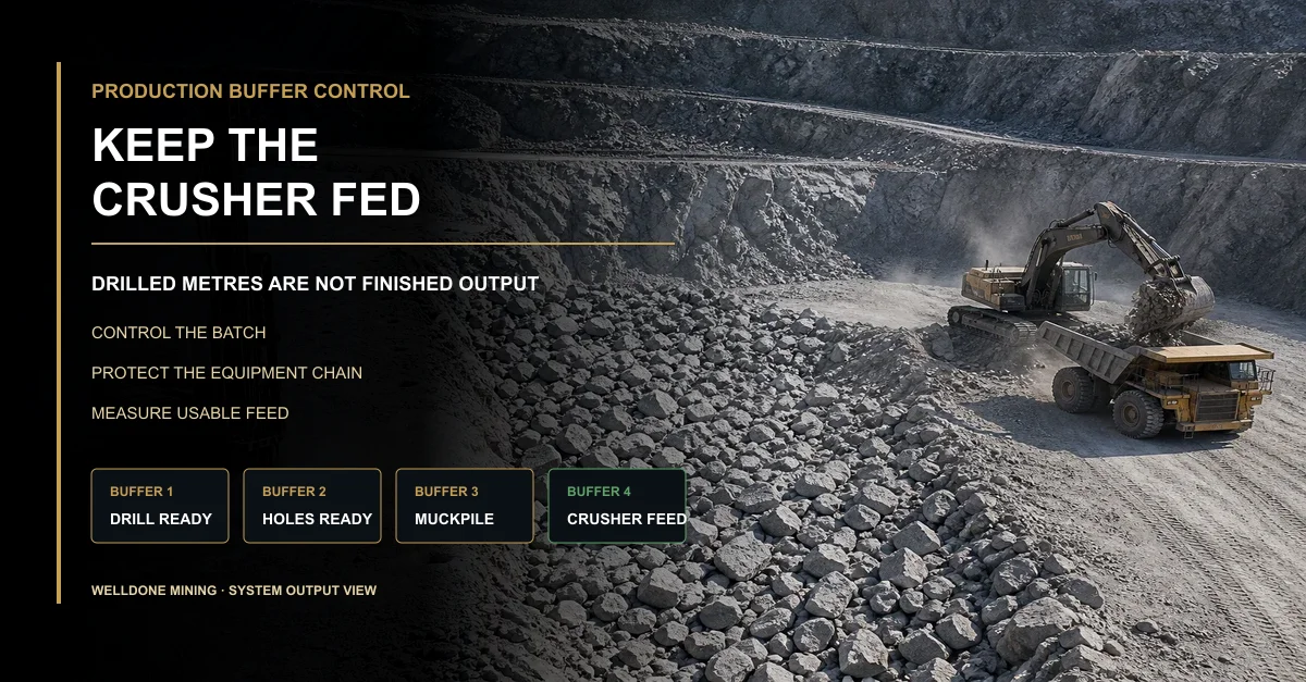
That is the practical value of quarry drilling FMEA: failure becomes visible before it reaches the muckpile or crusher.
Why Welldone Mining
Welldone Mining treats quarry drilling equipment as one connected duty chain. Rig selection is reviewed with compressor demand, air path, hammer, bit, rods, adapters, service items, measuring needs, critical spares, commissioning, and operating support.
Site-based matching: Formation, diameter, depth, access, environment, and production requirements shape the package.Interface control: Compatibility, connections, wear, maintenance, recovery, and starter spares are reviewed with the main equipment.Evidence-led support: Troubleshooting connects equipment condition and hole delivery with batch-linked field outcomes.
Review the verified quarry drilling solution for quarry applications, drilling methods, equipment categories, and operating constraints.
Conclusion
A failure does not need to stop the rig. It only needs to remove control from the intended hole geometry, equipment duty, or evidence chain.
Map credible failure modes before mobilisation. Put prevention and detection at the closest practical control point. Define hold triggers before production pressure appears. Then connect blast and downstream effects to supported mechanisms rather than assumptions.
If every major machine is still running tomorrow, which small signal would prove that your drilling system has already started to fail—and who has the authority to act?
Frequently Asked Questions
What does FMEA mean in a quarry drilling project? It is a structured review of how pattern, equipment, execution, measurement, and evidence controls can fail, what effects may follow, how failure is detected, and what response is required.
Is FMEA only for machine breakdowns? No. It should also cover survey revisions, setup, air delivery, tool interfaces, hole condition, measurement, blocked and replacement holes, record ownership, and downstream traceability.
Should every abnormal signal stop the complete quarry? No. The control plan can hold one hole, row, workfront, or equipment chain according to the affected risk and the authority of qualified site parties.
Can blast results identify the exact drilling failure? Not by themselves. Blast and downstream outcomes provide effects that must be compared with geology, as-drilled evidence, equipment state, regulated inputs, and operating context.
Can Welldone Mining approve our blast-design FMEA? Welldone Mining can support equipment matching and drilling-side controls. Qualified local professionals must define and approve site-specific blast design, regulated criteria, and execution.
Written by: Welldone Mining Engineering TeamTechnical review: Mostafa Ansary, Technical Sales Manager — mechanical design and production-management background with 15 years in machinery and production fieldsMarket context: Welldone Mining Project Support Team — quarry equipment matching , failure prevention, and operating-evidence requirements
Identify the Failure Mode Before It Reaches the Blast
Send the formation, hole diameter and depth, bench geometry, approved pattern basis, air requirement, equipment list, recurring exceptions, and observed downstream effects. Welldone Mining can help review the drilling-side package and control interfaces.
Website: www.welldonemining.com
Email: info@welldonemining.com