Quarry Turnkey Tolerance Stack-Up: Hole Pattern, Equipment List, and Blast Efficiency
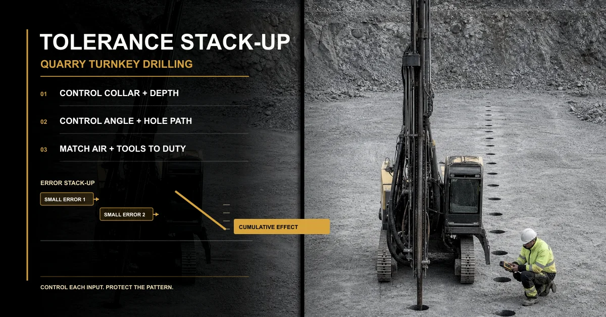
A quarry pattern can look correct at the collar while the geometry at the bottom of the bench has already changed. Collar offset, depth error, mast angle, hole deviation, cleaning quality, and tool wear may each appear manageable alone. Combined, they can change the effective burden, leave toe, create oversize, and destabilize crusher feed.
Table of Contents
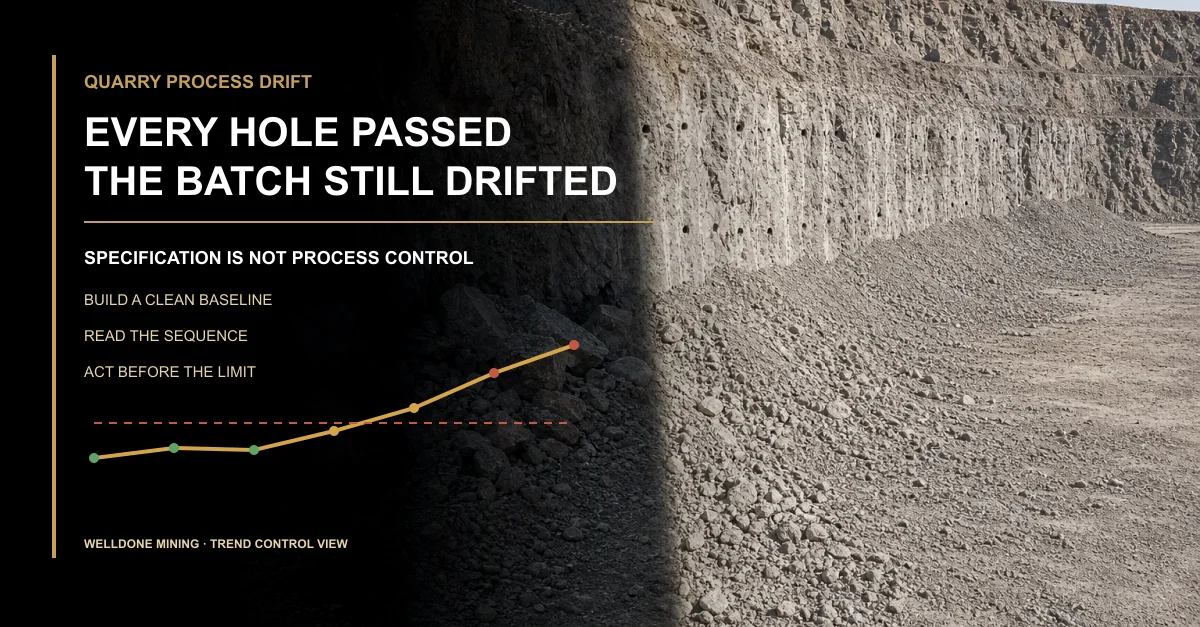
Every Hole Passed — the Bench Still Failed
The collar survey looked acceptable. Depth logs were complete. The rig finished the row without a major stoppage.
After the blast, the loader found a hard strip at the floor and several coarse zones near the same end of the bench. Each individual record looked close to plan, yet the combined hole geometry had moved away from the design intent.
No single dramatic failure. Several small ones in the same direction.
The real question is not whether one tolerance was exceeded. It is whether the accumulated position of the hole at depth still preserved the intended rock geometry.
What Tolerance Stack-Up Means in a Quarry
Tolerance stack-up is the cumulative effect of several small deviations. In manufacturing, dimensions accumulate across parts. In quarry drilling , collar position, depth, angle, hole path, cleaning condition, and actual usable hole length accumulate inside the rock.
The design may specify one relationship between holes and the free face. The rock only responds to the geometry that was actually drilled and prepared.
A common mistake is to review each record in isolation. Five individually explainable deviations can still combine into one unacceptable local result.
Error Source
What Changes in the Rock
Visible Field Consequence
Evidence Needed
Collar position
The starting burden or spacing differs from the controlled layout
Local coarse zone, inconsistent breakage, or uneven burden distribution
Survey reference, collar coordinates, and linked hole IDs
Depth delivery
The bottom position and intended floor relationship change
Toe, high floor, difficult digging, or extra cleanup
Planned depth, measured depth, reference elevation, and blocked-hole notes
Mast angle and alignment
The hole enters the bench on a different trajectory
Bottom spacing differs even when collars appear correct
Setup check, target inclination, and field verification
Hole deviation
The path drifts from the intended plane through depth
Concentrated coarse rock, uneven floor, or irregular fragmentation bands
Deviation measurement where required, geological notes, and affected location
Cleaning and usable hole condition
The effective prepared geometry may differ from the logged depth
Inconsistent hole condition, delays, or unreliable downstream comparison
Air-path condition, cuttings return, blockage record, and final-hole check
Hole Pattern Design: Control Geometry From Collar to Toe
Burden and spacing are usually drawn at the bench surface. Their operational meaning continues below the collar. If the hole path moves, the effective relationship between adjacent holes and the free face moves with it.
The pattern review therefore needs more than a grid. It needs the bench reference, target depth, inclination, expected geological behaviour, measurement method, exception rule, and a clear way to connect each as-drilled hole to the approved plan.
In my view, the strongest pattern document is not the one with the most precise numbers. It is the one that states which variables must be measured before the team claims the geometry was delivered.
The verified quarry blast hole pattern design guide explains burden, spacing, subdrill, stemming, deviation, air demand, and equipment matching. Final site-specific design and regulated blast decisions remain with qualified professionals.
Pattern Control
Design Question
Field Control
Escalation Condition
Collar grid
Which survey reference defines the planned grid?
Mark, verify, and record the actual collar before drilling
Access or setup forces a relocation outside the agreed rule
Bottom geometry
How should target depth and inclination relate to the intended floor?
Use a consistent reference and record uncertain or blocked holes
Measured depth does not prove the intended bottom position
Hole path
Which geological and drilling conditions could increase deviation risk?
Check alignment, setup, tool condition, and deviation evidence where required
A pattern of directional error appears across a row or zone
Exceptions
Who approves replacement, abandoned, or corrected holes?
Keep original and replacement identities linked to the final layout
The final hole arrangement cannot be reconstructed from the record
Equipment List: Assign a Control to Every Error Source
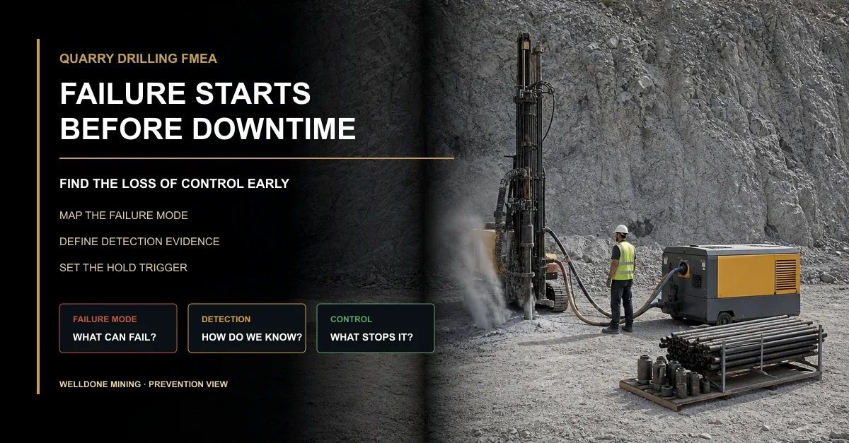
The equipment list should not be a catalogue of large machines. It should show how the project controls setup, air delivery, hole path, cleaning, tool wear, measurement, maintenance, and recovery from exceptions.
The rig controls positioning and feed. The compressor and air path support the agreed drilling duty and cleaning. The hammer, bit, rods, and adapters transfer energy and influence stability. Survey and measuring tools make the final geometry visible.
The list also needs quantities, connections, wear limits, starter spares, service tools, and record ownership. A component that exists on the packing list but cannot be maintained or verified on site does not control the risk.
Welldone Mining’s verified customized drilling solution connects rigs, compressors, bits, rods, hammers, accessories, spares, and support to depth, diameter, formation, air demand, and working conditions.
Equipment Group
Tolerance or Variation Controlled
Minimum Scope Question
Failure Signal
Rig and setup system
Position, mast angle, feed stability, and repeatable setup
How are setup, reference, access, and operating limits checked?
Shift-to-shift angle variation or repeated setup correction
Compressor and air path
Stable duty, cuttings removal, and usable hole condition
Are pressure, flow, hoses, connections, leakage, and operating demand matched?
Poor cleaning, recurring blockage, heat, unstable drilling, or depth-related loss
Hammer, bit, rods, and adapters
Energy delivery, hole stability, connection integrity, and wear progression
Are formation, diameter, connection, wear criteria, and spare quantities defined?
Uneven wear, unstable penetration, short life, or recurring directional behaviour
Measurement and survey tools
Verification of collar, depth, angle, and exceptions
Who measures, with what method, at what frequency, and in which format?
The team cannot prove whether the geometry was delivered
Maintenance and starter spares
Performance drift caused by wear, leakage, damage, or delayed repair
Which parts, tools, checks, and response responsibilities are available on site?
Hole quality changes as wear accumulates or by operator shift
Blast Efficiency: Evaluate the Combined Effect
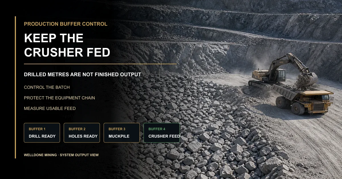
The blast result is where the tolerance stack becomes visible. Toe, coarse zones, irregular fragmentation, tight digging, oversize handling, and crusher interruption may show that the delivered geometry differed from the intended geometry.
These outcomes do not prove one cause. Geology, regulated blast inputs, free-face condition, loading, and crusher operation also matter. The purpose of the evaluation is to link a result to evidence, not to assign blame from appearance.
Use consistent batch identity and measurement. Map the outcome by zone, compare it with as-drilled records, and preserve downstream context before changing multiple inputs.
The verified guide to quarry blast efficiency evaluation covers fragmentation, oversize, toe, muckpile, compliance evidence, and repeatable comparison.
Efficiency Signal
What It May Reveal
Cross-Check
Decision Use
Toe or high floor
Bottom geometry, depth uncertainty, deviation, geology, or regulated-input issue
Floor survey, affected hole IDs, depth records, path evidence, and qualified blast review
Identify whether to correct drilling delivery, design assumptions, or another controlled input
Localized oversize
Local geometry change, geological boundary, or inconsistent regulated input
Oversize map, collar and hole-path record, geology, and batch identity
Test a zone-specific cause before changing the complete pattern
Irregular fragmentation band
Stacked variation across a row or depth interval
Row sequence, as-drilled geometry, tool condition, cleaning record, and geology
Locate whether the variation follows holes, rock, equipment condition, or regulated work
Slow loading or crusher disruption
Size, pile position, access, feed control, or plant condition
Muckpile observations, loader context, crusher status, and blast batch
Avoid treating every downstream loss as a pattern failure
Build a Tolerance Budget Before Production Drilling
A tolerance budget lists the variables that can move the delivered geometry and assigns a measurement, owner, trigger, and corrective response to each one.
It does not mean every variable receives the same numerical limit. Some controls are measured directly; others are managed through procedures, condition checks, or exception records. The project’s qualified design and operational teams must define the site-specific criteria.
More importantly, the budget should identify combinations. A small collar shift and a small directional drift that move in opposite directions may partly offset. The same deviations in the same direction may reinforce each other.
Tolerance-Budget Field
Required Definition
Owner
Trigger
Design variable
Controlled plan, reference, assumptions, and intended relationship in the rock
Qualified design party
Site condition or geometry no longer matches the approved basis
Field delivery
Measurement method, frequency, data format, and exception rule
Drilling, survey, and site-control teams
Repeated deviation, uncertain evidence, or local clustering
Equipment condition
Configuration, connection, wear, maintenance, and operating-condition checks
Supplier and operator within their contracted scopes
Performance drift, leakage, abnormal wear, or recurring instability
Result evidence
Batch identity, location, evaluation method, and downstream context
Production, survey, qualified blasting, loading, and crushing teams
Toe, oversize, inconsistent fragmentation, loading difficulty, or crusher loss
Use Field Evidence to Tighten the Right Input
The team should not tighten every tolerance after one poor result. That increases cost without proving which control matters.
Instead, map the outcome, compare the design and as-drilled records, inspect the equipment chain, rank supported hypotheses, and test one change under comparable conditions.
When the same symptom follows the same error source across more than one controlled batch, the project has evidence to tighten that input. When the symptom moves with geology or downstream operation, the response belongs elsewhere.
That is the practical value of tolerance stack-up: not tighter numbers everywhere, but tighter control where accumulated variation changes the quarry result.
Why Welldone Mining
Welldone Mining approaches the drilling package as a connected control system. Rig setup, compressor duty, air path, hammer, bit, rods, accessories, spares, commissioning, and operating support are matched to the formation and hole requirement.
Duty-based configuration: Equipment selection begins with formation, diameter, depth, access, environment, and production duty.Connected package review: Air, tooling, interfaces, maintenance, and records are considered with the rig.Evidence-based support: Troubleshooting uses site condition, equipment state, hole delivery, and exception evidence.
Review the verified quarry drilling solution for quarry applications, drilling methods, equipment categories, and operating constraints.
Conclusion
A quarry does not blast the drawing. It blasts the accumulated geometry delivered inside the rock.
Control the collar, depth, angle, path, cleaning, and tool condition as one chain. Then evaluate toe, oversize, fragmentation, loading, and crusher response against the same batch.
If every individual record is “close enough,” can your team still prove the combined hole geometry remains close enough at the bottom of the bench?
Frequently Asked Questions
What is tolerance stack-up in quarry drilling? It is the combined effect of collar, depth, angle, hole-path, cleaning, tooling, and measurement variations on the geometry actually delivered inside the bench.
Can each hole pass inspection while the pattern still performs poorly? Yes. Individual deviations may remain explainable while their directions and locations combine into a local geometry that differs materially from the design intent.
Why include the compressor in a hole-accuracy review? The compressor and air path affect drilling duty and cleaning. Unstable cleaning or air delivery can create uncertain final-hole conditions and inconsistent execution.
Does toe prove that hole depth was wrong? No. Depth delivery is one possible cause. Hole path, geology, design assumptions, regulated blast inputs, and measurement validity must also be reviewed.
Can Welldone Mining define site-specific blasting tolerances? Welldone Mining can support equipment matching and drilling-side evidence. Qualified local professionals must define and approve site-specific blast design and regulated criteria.
Written by: Welldone Mining Engineering TeamTechnical review: Mostafa Ansary, Technical Sales Manager — mechanical design and production-management background with 15 years in machinery and production fieldsMarket context: Welldone Mining Project Support Team — site-duty, equipment-matching, and operating-evidence requirements
Control the Combined Error Before It Reaches the Crusher
Send the formation, hole diameter and depth, bench geometry, approved pattern basis, air requirement, equipment list, and observed result. Welldone Mining can help review the drilling-side configuration and evidence plan.
Website: www.welldonemining.com
Email: info@welldonemining.com