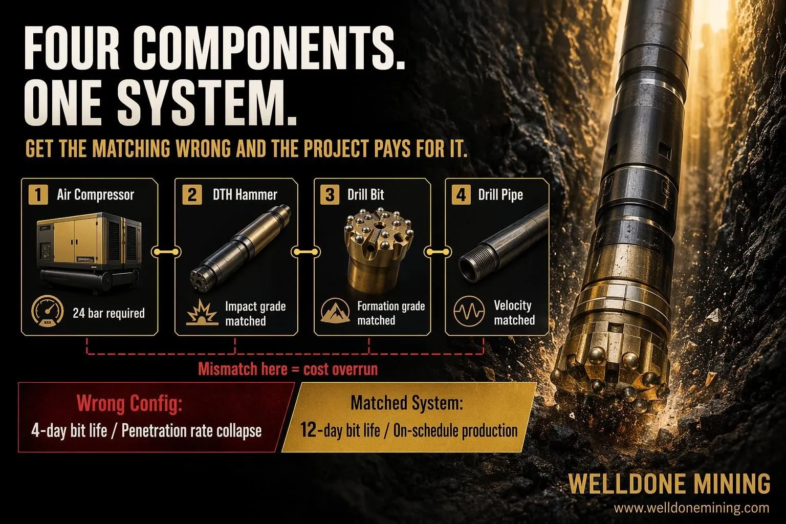
A contractor working a quarry project in East Africa called us three weeks into a six-week contract. His penetration rate had dropped from 12 meters per hour to 4. His DTH bits were lasting four days instead of the expected twelve. His compressor was running at maximum capacity and still not delivering adequate pressure at the hammer face. The project was behind schedule and the client was asking questions.
Every component he had purchased was from a reputable supplier. Nothing was defective. The problem was that those components had never been selected as a system. His compressor was sized for water well work at 17 bar. His hammer required 24 bar inlet pressure to deliver rated impact energy in the basalt formation he was drilling. His bit was a standard grade for medium-hard rock — the formation turned out to be hard crystalline basalt with a UCS above 180 MPa. And his drill pipe diameter was creating a velocity restriction that limited cuttings removal efficiency at depth.
Four separate purchasing decisions. Each reasonable in isolation. Together, a system that could not do the job the project required.
This article is a complete walkthrough of the DTH drilling system — what each component does, how the components interact, what happens when they are mismatched, and what information a contractor needs to confirm before committing an equipment configuration to a project.
What DTH Drilling Actually Is — and Why System Matching Matters
DTH stands for Down-The-Hole. In a DTH drilling system, the hammer is located at the bottom of the drill string, directly above the drill bit. Compressed air travels down the inside of the drill pipe, powers the hammer's reciprocating mechanism, drives the bit against the rock face with high-frequency percussive force, and then exits through the bit face to carry rock cuttings back up the annulus between the drill pipe and the borehole wall.
Every part of this process depends on every other part. The compressor determines how much air pressure and volume are available. The drill pipe diameter determines how much of that pressure reaches the hammer after accounting for friction losses through the string. The hammer converts the air pressure into impact energy — but only if the inlet pressure meets the hammer's minimum operating requirement. The bit breaks the rock — but only if the impact energy from the hammer is sufficient for the formation hardness, and only if the air volume exiting the bit is high enough to clear cuttings from the hole.
Change any one component without adjusting the others and the system performance changes — often dramatically.
| Component |
Primary Function |
Key Parameter |
Effect on System if Undersized |
| Air compressor |
Supplies pressure and volume to the system |
Working pressure (bar) and airflow (m³/min) |
Hammer starved of pressure, penetration rate collapses |
| DTH hammer |
Converts air pressure into percussive impact |
Minimum inlet pressure and impact frequency |
Insufficient impact energy for formation hardness |
| Drill bit |
Breaks rock by impact and rotation |
Carbide grade, button geometry, face design |
Premature wear, polished face, low penetration rate |
| Drill pipe |
Transmits air and rotation, returns cuttings |
Inner diameter, wall thickness, thread type |
Velocity restriction, poor cuttings removal, pipe wear |
The Air Compressor: The Foundation of the System
The air compressor is the energy source for the entire DTH system. Everything downstream depends on the pressure and volume it delivers — not at the compressor outlet, but at the hammer face after all the losses through the drill string.
Two parameters matter: working pressure in bar, and airflow volume in cubic meters per minute. Both must be matched to the application — and both degrade between the compressor and the hammer.
Pressure drops through the drill string due to pipe friction. The longer the drill string and the smaller the pipe inner diameter, the more pressure is lost before the air reaches the hammer. A compressor delivering 24 bar at its outlet may only be delivering 20 bar at the hammer face at 150 meters of drill string, depending on pipe diameter. If the hammer requires 22 bar minimum inlet pressure to produce its rated impact frequency, it will underperform — and the operator will see slow penetration and bit polishing but may not immediately identify the cause as inadequate hammer inlet pressure.
Airflow volume determines cuttings removal efficiency. The air exiting the bit face must travel up the annulus between the drill pipe and the borehole wall fast enough to carry cuttings to surface. That uphole velocity depends on the airflow volume and the annulus cross-section area, which is determined by hole diameter and pipe outer diameter. Larger holes require more airflow to maintain adequate uphole velocity. If the compressor cannot provide that volume, cuttings accumulate at the bottom of the hole, the bit regrinds cuttings instead of fresh rock, and penetration rate falls — while bit wear accelerates because the bit is working twice as hard for half the progress.
| Hole Diameter |
Minimum Uphole Velocity |
Approximate Airflow Required |
Typical Compressor Range |
| 76 to 89mm |
15 to 20 m/s |
8 to 12 m³/min |
10 to 15 bar, 10 to 14 m³/min |
| 100 to 115mm |
15 to 20 m/s |
12 to 18 m³/min |
17 to 24 bar, 14 to 20 m³/min |
| 127 to 152mm |
15 to 20 m/s |
20 to 30 m³/min |
24 to 30 bar, 20 to 35 m³/min |
The DTH Hammer: Matching Impact Energy to Formation
The DTH hammer sits at the bottom of the drill string and converts the compressed air from the compressor into high-frequency percussive energy that drives the drill bit against the rock face. It operates as a pneumatic piston — air pressure pushes the piston down onto the bit shank, the bit impacts the rock, and then the air reverses the piston for the next stroke.
Hammer size is defined by the drill bit diameter it accepts — a 4-inch hammer accepts bits in the 100 to 115mm range, a 5-inch hammer accepts bits in the 127 to 140mm range, and so on. Within each size class, hammers are available in different pressure ratings — low pressure hammers for compressors in the 10 to 14 bar range, medium pressure for 17 to 22 bar, and high pressure for 24 to 30 bar systems.
The impact energy a hammer delivers per blow is a function of piston mass, stroke length, and air pressure. Higher inlet pressure produces more energy per blow, up to the hammer's design maximum. A hammer running below its minimum inlet pressure does not just produce less energy — it produces significantly less energy, because the piston does not complete its full stroke before the air reverses. The relationship between inlet pressure and impact energy is not linear. It drops sharply below the minimum operating pressure.
This is why using a low-pressure compressor with a medium or high-pressure hammer is such a damaging mismatch. The hammer operates in an inefficient partial-stroke mode, impact energy is far below rated specification, and the bit is being driven against the rock without enough force to fracture it efficiently. The bit wears by abrasion rather than fracture — which is the most destructive and least productive form of bit wear.
What to Confirm When Selecting a DTH Hammer
- Minimum and maximum inlet air pressure for the hammer model.
- Required airflow volume at operating pressure — some hammers are more air-efficient than others at the same pressure rating.
- Impact energy per blow at the compressor's actual operating pressure — not the hammer's rated maximum.
- Hammer body length and weight — affects drill string balance and rotation torque requirement on the rig.
- Flushing port design — affects cuttings removal behavior, particularly in water-bearing formations.
The Drill Bit: Formation Matching Is Not Optional
The drill bit is the component in direct contact with the rock. It is also the component that bears the full consequence of every mismatch in the system above it — inadequate hammer pressure, poor cuttings removal, wrong carbide grade for the formation. When the system is misconfigured, the bit is where the damage appears first and most visibly.
DTH bits for hard rock applications use tungsten carbide buttons pressed into the steel bit body. The carbide buttons are the cutting elements — they break rock by impact when the hammer drives the bit face against the rock surface, and by abrasion as the bit rotates between impacts. The carbide grade, button size, button geometry, and face design all affect how the bit performs in a specific formation.
Hard crystalline formations — basalt, granite, hard limestone with high silica content — require a hard carbide grade with small-diameter buttons and a high button density. The small buttons concentrate impact energy over a smaller contact area, which increases the stress applied to the rock per impact and improves fracture efficiency. Softer formations — sedimentary limestone, sandstone, coal measure rocks — can use a tougher carbide grade with larger buttons that resist chipping in abrasive conditions but cover more area per blow.
Using a soft-formation bit in hard rock does not just reduce penetration rate. It causes rapid button wear — the carbide buttons flatten and lose their profile, which reduces penetration efficiency further, which means the bit dwells longer on the same rock surface, which accelerates wear even more. A bit that should last 400 meters in the correct formation may last 80 meters in the wrong one. The contractor does not always recognize that the bit grade is the cause — they see the worn bit and order the same grade again.
| Formation Type |
UCS Range (MPa) |
Recommended Carbide Grade |
Button Geometry |
| Soft sedimentary (limestone, sandstone) |
40 to 80 |
Tough grade, impact resistant |
Large dome buttons, wide spacing |
| Medium hard (hard limestone, dolomite) |
80 to 140 |
Medium grade, balanced wear and toughness |
Medium ballistic buttons |
| Hard crystalline (granite, basalt) |
140 to 200+ |
Hard grade, wear resistant |
Small ballistic buttons, high density |
| Highly abrasive (quartzite, siliceous formations) |
150 to 250+ |
Premium hard grade with cobalt binder |
Small spherical or chisel buttons |
The Drill Pipe: The Variable Nobody Talks About Until It Causes a Problem
Drill pipe in a DTH system has three functions. It transmits rotation from the rig head to the hammer and bit. It carries compressed air from the compressor down to the hammer. And it provides the outer boundary of the annulus through which cuttings travel back to surface.
Drill pipe inner diameter affects how much pressure is lost between the compressor and the hammer. A pipe with a smaller inner diameter creates more friction resistance to airflow, which means more pressure loss for the same airflow rate. Over a 150-meter drill string, the difference between 51mm ID pipe and 57mm ID pipe can be 2 to 3 bar of pressure loss — which may be the difference between the hammer operating above or below its minimum inlet pressure.
Drill pipe outer diameter, combined with hole diameter, determines the annulus cross-section area — which controls uphole velocity for cuttings removal. A pipe that is too large relative to the hole diameter creates a narrow annulus with high cuttings concentration and poor clearance. A pipe that is too small relative to the hole diameter reduces uphole velocity below the minimum needed to carry cuttings to surface, causing cuttings to fall back and accumulate.
Actually, drill pipe selection is the variable that most contractors treat as fixed — they use the pipe that came with the rig, or the pipe that was left over from the previous project — without checking whether it is appropriate for the current hole diameter, depth, and compressor combination. The consequences of the wrong pipe selection accumulate silently through the project, showing up as slightly lower penetration rates, slightly higher compressor load, slightly faster bit wear — none of which are traced to the pipe until the project economics are already damaged.
How to Build a Matched DTH System: The Correct Configuration Sequence
The correct sequence for configuring a DTH drilling system starts with the formation and the hole specification — not with the equipment the contractor already owns.
Step 1: Confirm the formation. Get UCS data if available. If not, get local drilling records from contractors who have worked the same geology. Identify the dominant formation type and estimate its hardness range. This determines bit grade.
Step 2: Confirm the hole specification. Hole diameter and target depth determine the required compressor airflow volume for cuttings removal and the hammer size range. They also determine the drill pipe outer diameter range compatible with the hole.
Step 3: Select the hammer. Based on the hole diameter and the formation hardness, select a hammer size and pressure rating. The hammer's minimum inlet pressure requirement determines the compressor specification.
Step 4: Size the compressor. The compressor must deliver the hammer's required inlet pressure at the hammer face — after accounting for pressure drop through the drill string length at the target depth. It must also deliver the airflow volume required for adequate cuttings removal at the hole diameter. Both conditions must be met simultaneously.
Step 5: Select the drill pipe. Choose inner diameter to minimize pressure loss through the string while staying within the hammer's thread connection requirement. Choose outer diameter to maintain adequate annulus area for cuttings removal at the target hole diameter.
Step 6: Confirm bit grade. Select the carbide grade and button geometry matched to the confirmed formation UCS and the hammer impact energy at the confirmed compressor pressure.
| Configuration Step |
Input Required |
Output Decision |
Common Mistake |
| 1. Formation assessment |
UCS data or local drilling records |
Bit carbide grade selection |
Visual assessment instead of test data |
| 2. Hole specification |
Diameter and target depth |
Compressor airflow requirement and hammer size |
Using the bit size from previous project |
| 3. Hammer selection |
Hole diameter and formation hardness |
Minimum compressor pressure specification |
Selecting hammer before knowing compressor capability |
| 4. Compressor sizing |
Hammer inlet requirement plus pipe losses at depth |
Compressor pressure and volume specification |
Sizing for surface pressure, not hammer face pressure |
| 5. Drill pipe selection |
Hole diameter, depth, hammer thread |
Pipe OD and ID specification |
Using existing pipe without checking annulus velocity |
| 6. Bit grade confirmation |
Formation UCS and hammer impact energy |
Carbide grade and button geometry |
Ordering same grade as previous project in different formation |
Consumable Planning: Building the Budget Around Real Bit Life
In a matched DTH system drilling the right formation at the right parameters, bit life is predictable within a reasonable range. A hard rock bit in hard crystalline basalt at the correct compressor pressure and penetration rate might last 200 to 350 meters. The same bit in medium-hard limestone at the same parameters might last 500 to 700 meters. These are not precise figures — they vary with exact formation hardness, compressor consistency, and operator technique — but they give a basis for consumable budgeting.
In a mismatched system, bit life is not predictable. A bit that is being driven by a hammer with insufficient inlet pressure will abrade rather than fracture. A bit in the wrong carbide grade for the formation will wear at an accelerated rate that does not stabilize — each wear cycle damages the carbide surface further, and the rate of wear increases as the bit face loses its profile.
The practical implication for project budgeting is straightforward: get formation data before finalizing the consumable budget, match the bit grade to that data, and build the quantity estimate around realistic bit life for the matched combination — not around bit life from a previous project in a different formation.
I believe the single most expensive mistake in DTH drilling project budgeting is estimating consumable quantities based on historical data from a different formation type. The contractor who drilled water wells in East African sedimentary rock for three years has good data on bit life in that context. That data is not transferable to a hard limestone quarry in the Middle East or a granite formation in West Africa without adjustment for formation hardness.
Remote Site Logistics: Stock Before You Mobilize
For projects in remote locations — rural Africa, interior Pakistan, mountain sites in Central Asia — the lead time for replacement drilling consumables from overseas suppliers is typically three to five weeks, including production, shipping, and customs clearance. In some markets, specialized DTH bit grades may not be available locally at all.
A project that runs out of the correct bit grade at week three of a six-week contract, and then waits four weeks for replacement stock, does not recover. The daily cost of idle equipment, idle crew, and contract penalties exceeds the cost of carrying surplus consumable stock by a significant margin in almost every scenario.
The practical standard for remote projects is to mobilize with consumable stock equivalent to 150 percent of the estimated project consumption — based on the formation-matched bit life estimate, not the optimistic estimate. The surplus comes home if the project goes well. The deficit does not come home at all.
Why Welldone Mining
Welldone Mining provides DTH drilling rigs, crawler drilling platforms, air compressors, DTH hammers, drill bits, drill rods, and accessories for quarry, mining, water well, and customized drilling projects. We configure complete drilling systems — not component lists.
When a contractor approaches us for an equipment package, we ask for formation data, hole diameter, target depth, required daily production in meters, ambient temperature range, and project duration. Those inputs determine every component in the package — compressor size, hammer grade, bit selection, pipe specification, and consumable quantity. A contractor who brings us that information leaves with a configuration that is built for the project they are actually doing.
For contractors who do not have formation data before mobilization, we help identify what information to collect — and how to interpret it — so the configuration decision is made on real data rather than assumptions that the project will later disprove at the contractor's expense.
- Customized Drilling Solution — formation-specific DTH system configurations combining compressor, hammer, bit, and drill pipe selection for complex or variable geology projects.
- Quarry Drilling Solution — blast hole and hard rock quarry configurations for construction aggregate and open-pit mining applications.
- Water Well Drilling Solution — complete configured systems for borehole and deep well projects across East Africa, South Asia, and the Middle East.
Related Equipment
DTH Hammer (Low, Medium, and High Pressure) — available in 3.5-inch through 8-inch sizes, matched to compressor pressure range and hole diameter. Hard rock and standard grades for different formation UCS ranges.
DTH Drill Bit (Formation-Matched) — button bits in standard, hard rock, and premium carbide grades. Available in flat face, concave face, and convex face designs for different formation types and cuttings removal requirements.
Air Compressor (Diesel and Electric) — sized to hammer inlet pressure requirement at target depth, with airflow volume matched to hole diameter. Diesel configurations for remote and mobile sites. High-pressure configurations for hard rock quarry and deep borehole applications.
Drill Pipe and Accessories — matched to rig thread type, hammer connection, hole diameter, and target depth. Includes stabilizers, sub-adapters, and crossover subs for different configuration requirements.
Crawler DTH Drilling Rig — available in configurations for water well, quarry, and blast hole applications. Matched to compressor output, hammer size, and hole diameter range of the target project type.
Conclusion
A DTH drilling system is not four separate purchasing decisions. It is one system decision made four times — and if any one of those four decisions is not matched to the other three, the whole system underperforms in ways that are expensive and difficult to diagnose once the equipment is on site.
The contractor in East Africa whose project fell apart in week three did not buy bad equipment. He bought equipment that was not configured as a system for his formation, his hole size, and his depth. The cost of that mismatch — in lost production, in replacement bits, in contract penalties, in damage to the client relationship — was many times the cost of getting the configuration right before mobilization.
Formation data. Hole specification. Hammer selection. Compressor sizing. Pipe selection. Bit grade confirmation. In that order. Every time. That sequence is not bureaucratic caution. It is the difference between a project that finishes on schedule and one that teaches an expensive lesson about system matching.
If you are configuring a DTH drilling system for an upcoming project, share your formation type, hole diameter, target depth, required daily production, and compressor specifications. Welldone Mining will verify whether your current configuration is matched for the project — and identify any adjustments needed before you mobilize.
Website: www.welldonemining.com
Email: info@welldonemining.com